Disclaimer The following are notes collected for myself and in service of building my own amps. LETHAL voltages exist within tube amplifiers so be careful. The majority of this information is pulled from the Valve Wizard and the videos of Psionic Audio. Buy the books, subscribe, etc.
Grounding #
Grounding is a deep subject, one I’ve struggled with since I started building pedals 15 years ago. The Valvewizard pdf on grounding is a great resource but sometimes it can be useful to see real schematics and an implementation to better understand what the theory looks like in practice. The best advice I have is to keep paths to ground as short as possible within a gain stage and limit the number of places that ground is made to the chassis. Ensure grounds are made securely e.g. via a toothed solder lug with a nyloc nut or tight jacks with lock washers.
Single Gain Stage #
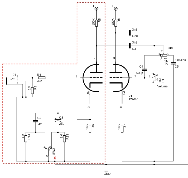
The components contained in the red polygon make up a single triode gain stage:

Fig 1: Single Triode Ground Arrangement
- Any grounds for a gain stage should be grounded to the cathode of that stage
- Every triode and any ground connections ahead of the grid of that triode should be referenced to the cathode’s ground point for that triode
- Triode stage cathodes should then be tied to the negative of their filter cap e.g. at point X in the above diagram.
- Coupling caps (or dc blocking caps) are the stage transition points. Note how the grounds on the right half of the diagram are drawn together.
- Run an individual wire to the filter cap negative per gain stage e.g. the single line below the red X to the ground symbol, which is physically tied to the negative of the filter cap supplying HT point E.

Fig 2: Ground Scheme as Implemented (right click > open image in new tab)
- Either connect:
- each stage filter cap to the chassis in sequence from noisiest to quietest like Fender, using the chassis as a large ground plane. You can see this technique in the image above. Note how each stage’s filter cap is placed physically close to that stage.
- filter cap negatives in sequence to a point at the input jack (except for the reservoir cap)
- All cap negatives should be tied to ground in order i.e. from the reservoir toward the input with their ground point as close to the cap negative as possible.
- When running with a single bus wire, use something VERY thick like 14 AWG since there is potentially substantial current flowing through that ground bus
- Only ground the bus to chassis at the input jack to avoid introducing ground loops
- The reservoir cap and transformer HT center tap should ground to a dedicated point with nice short wires. This ground point is the noisiest in the amp and can be seen on the far left in the figure above.
- Use dedicated ground lugs when grounding to the chassis i.e. don’t use transformer bolts, etc. since these are more likely to loosen and lose ground reference. Again, you can see the dedicated ground points with nyloc nuts to insure a solid ground connection.
- Don’t ground the pot lugs to the back of the pots or to the chassis ground. Run to the cathode ground and then a single wire from the filter cap to the chassis.
- Ground screen grid supply to the power tube ground point
- Output jacks
- Run the power transformer ground to the sleeve of the output jack with a dedicated wire
- On amps with global negative feedback, you need a ground from the output jacks.
- This ground should be in the form of a wire from the sleeve connection of the output jack to the preamp ground point where the phase inverter common connections are grounded or to the ground of the portion of the circuit where the global feedback from the tip connection of the output jack is connected.
- Heater artificial center tap and real center tap ground should go to the HT center tap / reservoir cap ground point, unless you are using an “elevated” filament reference voltage for hum reduction purposes.
- When using an elevated heater, the center tap is simply referenced to the elevation point as can be seen by the green wire on the far left of the figure above.
- Brad from Brad’s Guitar Garage suggests using an artificial center tap even if the transformer has a true center tap unless using elevated heaters. The artificial center tap resistors act as a fuse, which will limit current and burn instead of destroying the transformer if a heater short to ground occurs.
Wiring #

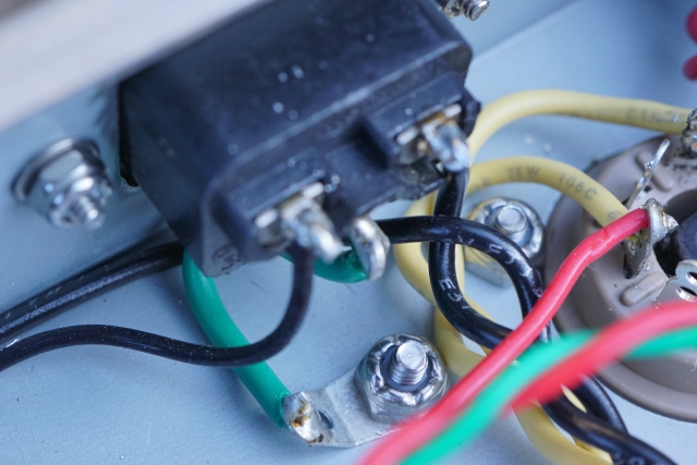
Fig 3: The chassis ground is the most important wire in the amp
- The most important wire in an amp is the chassis earth. Use an 18 AWG green or green with yellow striped wire to a dedicated chassis ground. Do not tie to transformer bolts, etc.

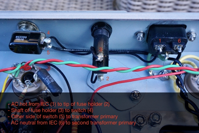
Fig 4: Proper AC input wiring
- Fuse wiring:
- AC hot from the wall should connect first to the fuse then to the switch. AC neutral is tied to the other power transformer primary connection or to the switch if using a DPDT power switch
- AC hot should go first to the end most point of the fuse holder since the mount point closer to the nut could be connected to the chassis, which could be an issue if a fuse is pulled while the amp is connected to the wall.
- Place resistors below or to the side of electrolytic caps when mounted on turrets since the cap is most likely to fail. This placement allows for easy removal of the cap without needing to remove the resistor.
- Keep longer wire runs away from other signals where possible (near ground for the given stage is okay) and run as close to the chassis as possible
- When mounting components on turrets, wrap component leads in a U shape (i.e 180 deg) and trim the excess (no need to do 360 deg wraps)
- When soldering turret mounted components, you want to be able to see each lead beneath the solder i.e. no need for a massive blob
- With el84s, don’t use free pins (pin 1, 6, or 8) to tie into anything. Screen resistors, etc. can just go into the air instead of across those free pins
- Screen grid resistors get hot so move them away from the tube socket as much as possible e.g. on the side of the socket as opposed to directly above the tube
- You can see an example in Figure 4. The 5W Vishay/Dale resistor is mounted to a tag strip.
- Watch long wire runs around high voltage DC and signal carrying AC which can induce noise onto those runs
- Orient components such that their values are visible when installed
- Use shielded wire on input jacks and ideally on pots
- Keep any transformer wires connected to the top of the board so that the board does not need to be lifted when repairing or replacing the transformer
- Keep triode wires together and at right angles to any heater wires
- The grid connection is the most important in terms of noise (not surprising given that it’s the input to the gain stage).
- Use shielded cable on reverb send if long run is needed
Mechanical #

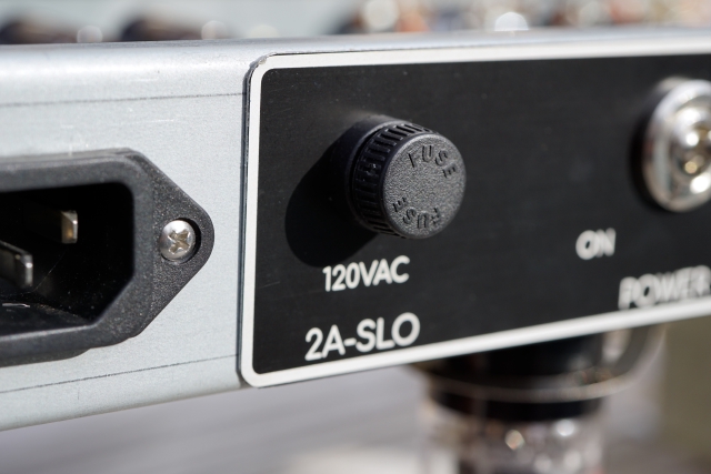
Fig 5: Low Profile Fuse Holder
- Prefer small “low profile” fuse holders such as the above so you don’t break them off in transit especially on a head
- Use lock nuts wherever possible especially on tube socket and transformer mounting bolts
- Use tooth washers on jacks and pots to limit the effects of mechanical stress (e.g. jacks coming loose) on wires. Toothed washers also help insure components maintain good electrical connection to the chassis e.g. when using the sleeve for grounding.
- Watch lead lengths on smaller capacitors (especially ceramic or mica) since the leads do not provide much mechanical support
- OT and PT should be rotated 90 degrees to keep the transformer coil orientation in perpendicular planes. Increase distance between the transformers as much as possible
- Keep transformers away from other mounting hardware ie you should be able to access all screws without dismounting the transformers
- When drilling wire pass-through holes on the board, use a chamfered bit to ensure no abrasion between the board and the wire
- Transformer mounting hardware:
- stainless screws, compression washers then washer then flange of the transformer
- fender washers, stainless nyloc nuts, and at least 2 exposed threads from the mounting bolt
- Use neoprene grommets not rubber as the rubber will degrade
Misc #
- Check DC and AC voltage rating on switches. Standby may have quite a lot of DC voltage. If so, the switch will need to be rated for that DC voltage (not AC)